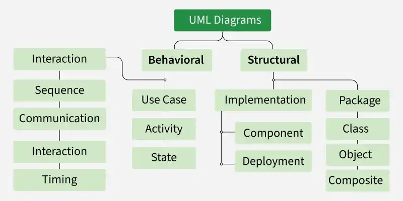
Types of Schemes
Database diagram (диаграмма базы данных)
A database schema is used to define the structure of data and the relationships between data elements. It describes the database tables (entities), the fields (attributes) they contain, and the relationships between tables. The schema serves as the foundation for the correct storage of data and the execution of queries within the system.
Use case diagram (диаграмма прецедентов)
Use case diagrams are used to identify the most important elements and processes that make up a system. The primary elements are called “actors” (эктор), and the processes are called “use cases” (прецедент). A use case diagram shows which actors interact with each use case.
Class diagram (диаграмма класса)
A class diagram is used to refine the use case diagram and define a detailed system design. A class diagram organizes the actors defined in the use case diagram into a set of interrelated classes. The relationship or association between classes can be either of the “is” or “has” type. Each class in the class diagram is capable of providing certain functionality. These are called class methods. In addition, each class has a set of attributes that uniquely identify the class.
Object diagram (диаграмма объекта)
An object diagram is a specific type of class diagram. An object represents the state of a class at a specific point in time during the system’s operation. An object diagram represents the states of the system’s various classes and the relationships or associations between them at a specific point in time.
State Diagram (диаграмма состояния)
As the name suggests, a state diagram illustrates the various states that objects in a system go through during their lifecycle. Objects in the system change their state in response to events occurring within the system. In addition, the state diagram also shows the transition of an object’s state from its initial state to its final state in response to events affecting the system.
Activity diagram (диаграмма активности)
The flow of processes within the system is described using a state transition diagram. Similar to a state diagram, a state transition diagram consists of actions, transitions, initial and final states, and blocking conditions.
Sequence diagram (диаграмма последовательности)
A sequence diagram illustrates how objects in a system interact with one another. A key feature of a sequence diagram is its temporal order. In other words, it depicts the precise interaction between objects step by step. The various objects in a sequence diagram communicate with one another by exchanging “messages.”
Collaboration diagram (диаграмма взаимодействия)
A collaboration diagram groups interactions between different objects. Interactions are numbered, which allows you to track the order in which they occur. A collaboration diagram allows you to identify all possible interactions that connect each object to the others.
Component diagram (диаграмма развертывания)
A component diagram depicts the high-level components that make up a system. This diagram shows which components constitute the system and how they are related to one another. Deployment diagram: A deployment diagram depicts the runtime elements of an application.
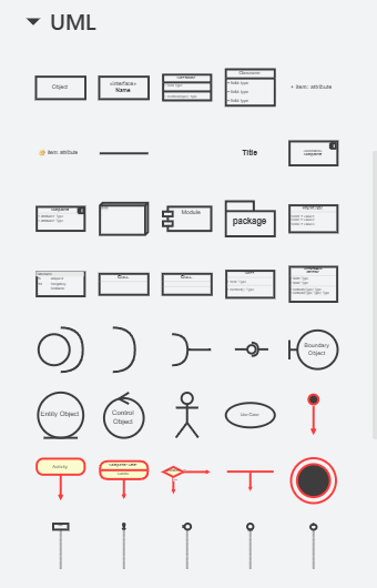
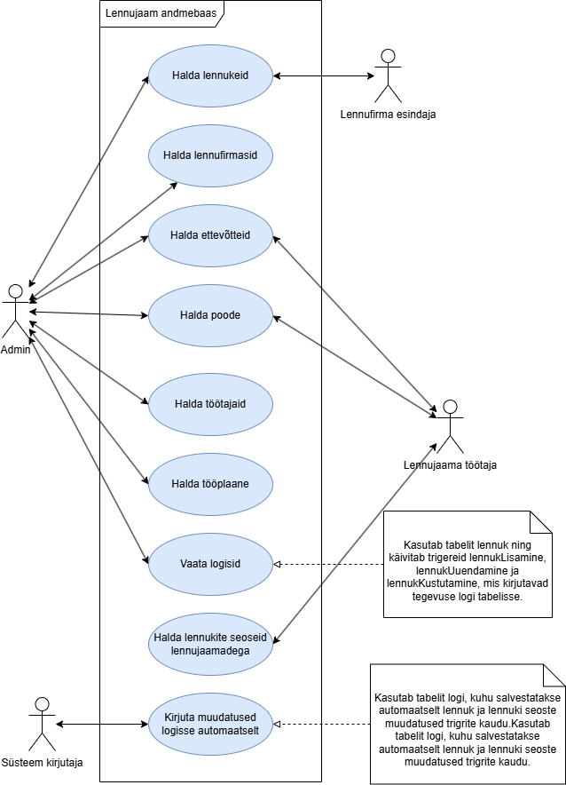
Use Case Diagram
An actor is a logically connected set of roles that are fulfilled in interaction through precedents or essence.
A use case is a description of a specific aspect of a system’s behavior from the user’s perspective.
Tags:
- In graphic form, the ector is depicted as a “human figure.”Precedents are indicated within ellipses. Precedents and successors are connected by lines or arrows.The direction of the arrows indicates from whom the service(s) is/are being requested.
- Pretsedendid on märgitud ellipsi sees. Pretsedendid ja ektorid on ühendatud joonte või nooltega.
- Noolte suund näitab, kellelt teenust/teenuseid taotletakse.
We use Drawio:
Airport database:
Activity Diagram
This diagram is intended for general process modeling, but it can also be used to represent algorithms that solve smaller problems.
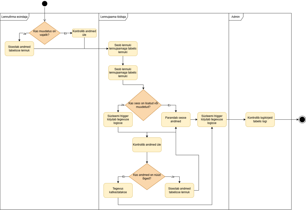
Toiming – ümarate nurkadega kast. See on üks ülesanne või käsk. Üks nool tuleb sisse ja üks läheb välja.
Voog – nool, mis näitab liikumise suunda järgmise sammuni.
Otsustuspunkt – romb ehk valikukoht. Siin küsitakse küsimus ja valitakse sobiv tee (nagu if-lause).
Lõpp – must täpp, kus algoritm saab läbi.
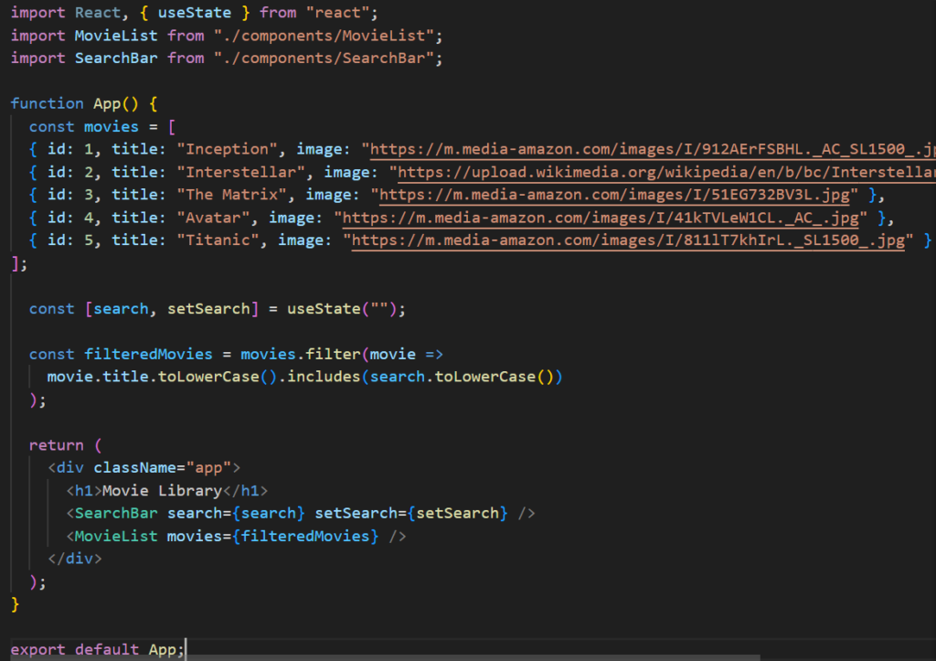
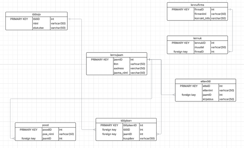
Database Diagram
Mudelid:
„entiteedid-seosed” – OLEMID – SEOSED
„entiteedid-atribuutid-seosed” – OLEMID – ATRIBUUDID – SEOSED
hierarhiline mudel – hierarhiline mudel
relatsiooniline mudel – relatsiooniline mudel / andmemudel
Olemid (Entities/Tables): Tavaliselt kujutatud ristkülikutena. Need tähistavad reaalset eluobjekti või kontseptsiooni, mille kohta andmeid kogutakse (nt Lennujaam, Lennuk, Lennufirma, Pood).
Seosed (Relationships): Jooned, mis ühendavad tabeleid ja näitavad, kuidas andmed on omavahel seotud (nt üks lennufirma võib omada mitu lennukit ja üks lennujaam võib olla seotud mitme ettevõtte, poe ja tööplaaniga).
Atribuudid (Attributes/Fields): Need on olemi omadused ehk tabeli veerud (nt lennujaama nimi, linn, aadress või lennuki mudel).
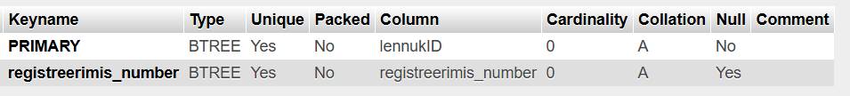
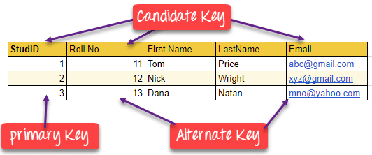
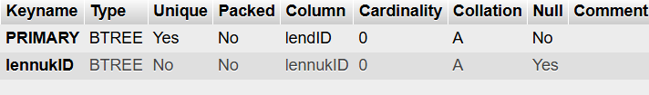
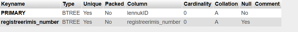
Võtmed (Keys):
Primaarvõti (Primary Key – PK): Unikaalne tunnus, mis tuvastab iga kirje tabelis (nt jaamID tabelis lennujaam).
Välisvõti (Foreign Key – FK): Viide teise tabeli primaarvõtmele, mis loobki seose kahe tabeli vahel (nt firmaID tabelis lennuk, mis viitab tabelile lennufirma).
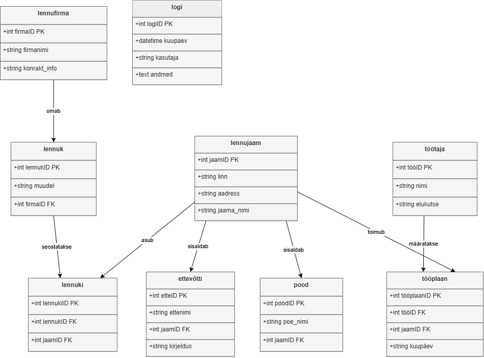
Class Diagram
Klassidiagramm on kogu süsteemi loogiline “arhitektuurne projekt”. See ei näita ainult seda, milliseid andmeid me säilitame, vaid ka seda, kuidas lennujaama infosüsteemi osad käituvad ja üksteisega suhtlevad.
Klassid (Classes): Kujutatakse ristkülikutena, mis on jagatud kolmeks sektsiooniks:
Nimi: Klassi nimetus (nt “Lennujaam”, “Lennuk”, “Lennufirma”, “Pood”).
Atribuudid (Attributes): Klassi omadused ehk andmed (nt jaama_nimi: String, linn: String, muudel: String).
Meetodid/Operatsioonid (Methods): Tegevused, mida see klass suudab teha (nt lisaLennuk(), muudaLennujaam(), kuvaLogi()).
Atribuudid (Attributes): Erinevalt andmebaasist määratakse klassidiagrammis ka andmete nähtavus:
- (Public): Kõigile nähtav.
– (Private): Nähtav ainult klassi siseselt.
(Protected): Nähtav klassile ja selle järeltulijatele.
Seosed (Relationships): Jooned, mis näitavad objektide vahelisi loogilisi ühendusi:
Assotsiatsioon (Association): Tavaline seos kahe klassi vahel (nt “Lennufirma” haldab “Lennukit”).
Pärilus (Inheritance/Generalization): Näitab “on-tüüpi” seost, kus alamklass pärib ülemklassi omadused.
Agregatsioon ja Kompositsioon: Näitavad “osa-tervik” suhet (nt “Lennujaam” koosneb seotud ettevõtetest, poodidest ja tööplaanidest).
Kordsus (Multiplicity): Näitab, mitu objekti seoses osaleb (nt 1 (üks), 0..* (null kuni mitu), 1..* (vähemalt üks)).
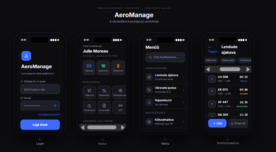
Vaade telefonile (valmistati figma’s):